


ESM-CB-AZ-FI2-BR-IO-158875 (Order no. 158875)
IO-Link Gateway with relay outputs for BP/BR switches
- IO-Link device for reading process and device data of BP/BR safety switches and transferring them to a higher-level control system
- Control of guard locking of BP/BR switches, depending on the switch used
- Compact version measuring only 18 mm in width
- Rail mounting
- LED status indicators
- Sensor circuit 1: connection of single- or dual-channel safety switches with floating contacts; short circuit, earth fault and ground fault detection
- Sensor circuit 2: connection of 2 safety outputs for BP/BR switches
- Use as safety relay with two safe outputs
- Start button and feedback loop can be connected
- Safety relay: use up to category 4 according to EN ISO 13849-1
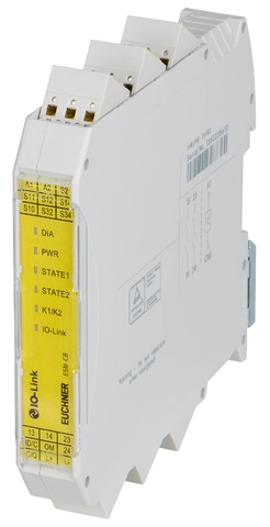
Description
Connection options
The following functions are possible given the corresponding wiring:
- Start input for automatic start or a monitored start button
- Monitoring of downstream relays or contactors (feedback loop)
- Short circuit monitoring to detect short circuits between the connecting cables and to shut down the outputs or prevent relay starting if necessary
- Earth fault/ground fault monitoring to detect short circuits between the connecting cables and earth or ground and to shut down the outputs or prevent relay starting if necessary.
Relay outputs
- The outputs are redundantly designed and electrically decoupled.
- Simultaneity monitoring of the safety outputs to monitor safety components over time.
- No time-delayed shutdown
Industry 4.0 ready
Process data are cyclically sent to the control system via IO-Link. These data include all status signals, such as the door or guard locking position, and the indication of whether a switch is in the limit range of the actuating range.
The process data are available to the control system after approx. 200 ms and can be used for the automation process.
Moreover, acyclical polling can be used to collect environmental data such as the internal switch temperature, the applied voltage or the ID of the transponder used, as well as other values.
Plug and Play series connection
- Connection for safety switches with BR technology without addressing the individual switches
- The wiring and configuration work is minimized.
Device data and events
The higher-level control system can poll more than 30 different items of information from the connected switches. Comprehensive data transmission via IO-Link enables targeted preventive maintenance, for example.
Simple implementation of innovative applications
Device data from the actuators used can be employed to detect individual rotary table positions or different containers, for example.
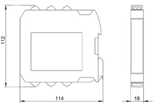
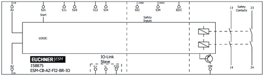
Dimensional drawings
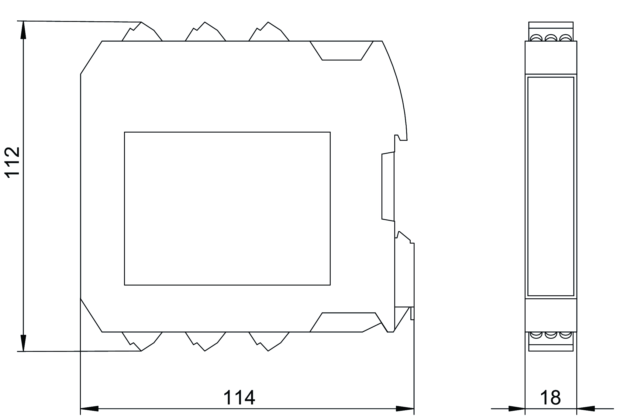
Connection examples
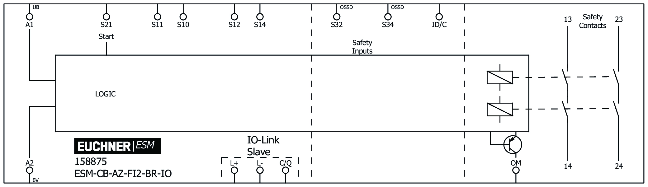
Technical data
Approvals


Operating and display elements
| LED display | |
| Status Indicator | DIA |
| Status Indicator | STATE2 |
| Status Indicator | IO-Link |
| Status Indicator | K1/K2 |
| Status Indicator | STATE1 |
| operating voltage | PWR |
Electrical connection values
| Power consumption | |
| at 24 V DC | 1.44 W |
| Connection cross section | 0.2 ... 1.5 mm² |
| Rated impulse voltage Uimp | |
| Leakage path/air gaps | |
| Over voltage category | II |
| Power dissipation | max. 6.45 W |
| Degree of contamination (external, according to EN 60947-1) | 2 |
| IO-Link | |
| Process data update | 5 ms |
| Power supply | |
| L /L- | 24 V DC -20% / +25% |
| Current consumption | |
| L /L- | 16 mA |
| Reverse polarity protection | Yes |
| Supply A1/A2 | |
| Rated insulation voltage Ui | 320 V |
| Rated impulse voltage Uimp | 4 kV |
| Operating voltage DC | |
| UB | 24 V DC -20% ... +25% |
| Duty cycle | 100 % |
| Current consumption | 60 mA |
| Reverse polarity protection | Yes |
| Diagnostic Input ID/C | |
| Current consumption | 30 mA |
| OM monitoring output | |
| Output type | PNP semiconductor output (non-safety-related) |
| Output voltage | |
| approx. | 22 V DC (UB - 2 V) |
| Switching current | max. 100 mA |
| Sensor Circuit S1: Inputs S12, S14 (safety-related inputs) | |
| Discrepancy time | ∞ |
| Input voltage | |
| 1-Signal | 11 ... 30 V DC |
| Test pulse duration | 1.5 ms |
| Test pulse interval | Test pulse rate = 5 × test pulse width |
| Sensor circuit S2: 2 safety inputs, S32 and S34 | |
| Discrepancy time | ∞ |
| Input voltage | |
| 1-Signal | 11 ... 30 V DC |
| Current consumption | max. 5 mA |
| Safety contacts 13/14, 23/24 | |
| Fuse | |
| external (safety circuit) according to EN 60269-1 | 6 AgG or 6 A circuit breaker (characteristic B or C) |
| Output type | |
| Normally open contact | 2, safety-related normally open contacts 13/14 and 23/24, 2 of each in series, redundantly wired internally, non-delayed, potential-free. |
| Utilization category | |
| AC-15 | 5A 230 V |
| DC-13 | 4A 24 V |
| Switching voltage | |
| AC/DC | 12 ... 250 V |
| Switching current | max. 6000 mA |
| Starting area: Entrance S21 | |
| Input voltage | 15 ... 27.6 V DC |
| Current consumption | 5 mA |
Mechanical values and environment
| Stripping length | 8 mm |
| Dimensions | 17.5 x 116.5 x 114.5 mm |
| Connection type | plug-in spring terminals |
| Installation orientation | vertical or horizontal |
| Storage temperature | -25 ... 70 °C |
| Atmospheric humidity | max. 75 % rH |
| Mounting type | Mounting rail TH 35 (EN IEC 60715) |
| Degree of protection | |
| IP20 | |
| IP54 (Installation location, min.) | |
| Ambient temperature | |
| (operation) | -25 ... 60 °C |
| Material | |
| Housing | PBT, gray |
| Contact | AgSnO2 |
| IO-Link | |
| Connection type | |
| C/Q | 1 Master's degree |
| Diagnostic Input ID/C | |
| Number of inputs | 1 |
| Safety contacts 13/14, 23/24 | |
| Mechanical life | |
| operating cycles | 10 x 10⁶ |
Characteristic values according to EN ISO 13849-1 and EN IEC 62061
| PL | Maximum SIL | PFHD | Category | Mission time | ||
|---|---|---|---|---|---|---|
| Monitoring of the guard position | At switching current ≤ 0.1 A at 24 V DC and max. 500,000 switching cycles 1/y | PL e | 3 | 1x10⁻⁹ | 4 | 20 y |
| At switching current ≤ 1 A at 24 V DC and max. 50,000 switching cycles/y | PL e | 3 | 1x10⁻⁹ | 4 | 20 y | |
| at switching current ≤ 4 A at 24 V DC and max. 15,000 switching cycles/y | PL e | 3 | 1x10⁻⁹ | 4 | 20 y |
Miscellaneous
| in compliance with | siehe Konformitätserklärung |
Interface
| IO-Link | |
| Data protocol | (COM3) |
| Data rate | 230 kbit/s |
| Cycle time | 5 ms |
Downloads
Complete package
Download all important documents with a single click.
Content:
- The operating instructions and any additions to the operating instructions or brief instructions
- Any data sheets to supplement the operating instructions
- The declaration of conformity
Single Documents


Other Documents


ePlan macros
Ordering data
| Ordernumber | 158875 |
| Item designation | ESM-CB-AZ-FI2-BR-IO-158875 |
| Gross weight | 0,231kg |
| Customs tariff number | 85371098 |
| ECLASS 11.0 | 27-24-26-07 Field bus, decentralized peripheral - basic device |