


CEM-I2-AY-U-C40-SA-128103 (Order no. 128103)
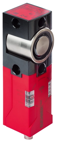
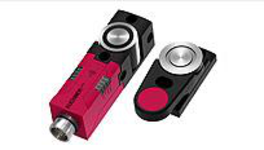
CEM-AY-C40 safety switch with guard locking, RFID, M12 plug connector(s)
- Unicode
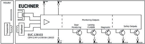
- Guard lock monitoring output OL
- Door Position (OT) Monitoring Output
- Diagnostic monitoring output OI
- Plug connector M12, 8-pin
Description
Guard locking principle
Operating current (power to lock): In a safety guard with guard locking based on the open-circuit current principle, the safety guard remains locked until the power supply to the guard locking solenoid is interrupted. This is also referred to as an electrical guard locking.
Adjustable adhesive force
The adhesive force can be adjusted to 0 N, approx. 30 N, and approx. 50 N (Delivery state) using a parameterization key (order no. 125481). The adhesive force is effective when the guard locking is inactive. This prevents, for example, the safety guard from opening on its own. The operating voltage UB must be applied for this to work.
Unicode evaluation
Each actuator is highly coded (unicode). The switch detects only taught-in actuators. Additional actuators can be taught-in.
Only the last actuator taught-in is detected.
Terminal assignment
| Plug connector (view of connection side) | Pin | Designation | Function | Potential | Connecting cable conductor coloring |
|---|---|---|---|---|---|
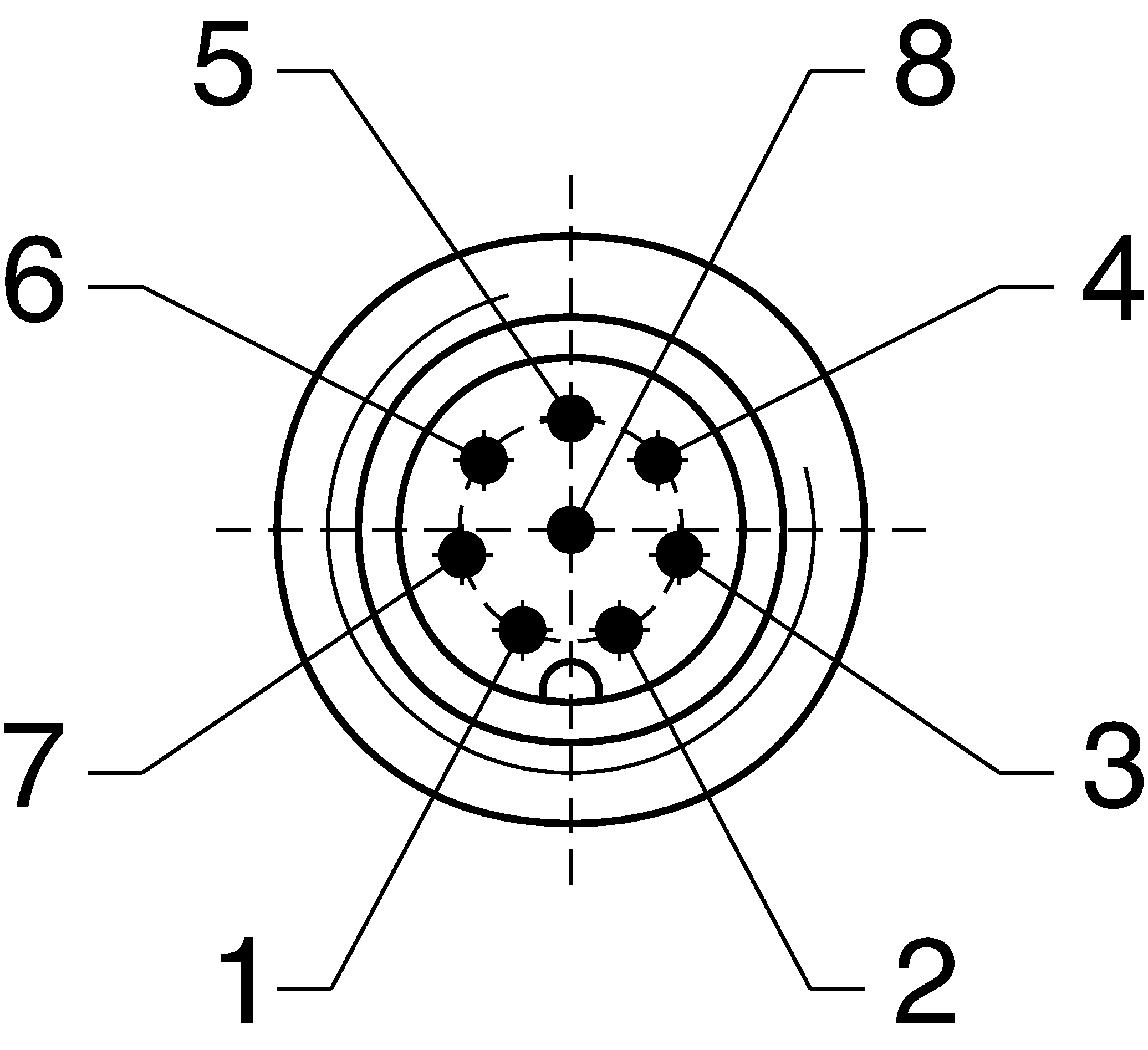 | 1 | IMP | Control Voltage for Guard Locking Solenoid | 24 V DC | WH |
| 2 | UB | Operating Voltage of the Electronics | 24 V DC | BN | |
| 3 | FO1A | Safety output, channel A | PNP | GN | |
| 4 | FO1B | Safety output, channel B | PNP | YE | |
| 5 | OI | Diagnostic monitoring output | PNP | GY | |
| 6 | OT | Door position monitoring output | PNP | PK | |
| 7 | OL | Guard lock monitoring output | PNP | BU | |
| 8 | 0 V UB | Operating Voltage for Electronics and Magnet | 0 V DC | RD |
Accessories required
Actuator is not included.
Dimensional drawings
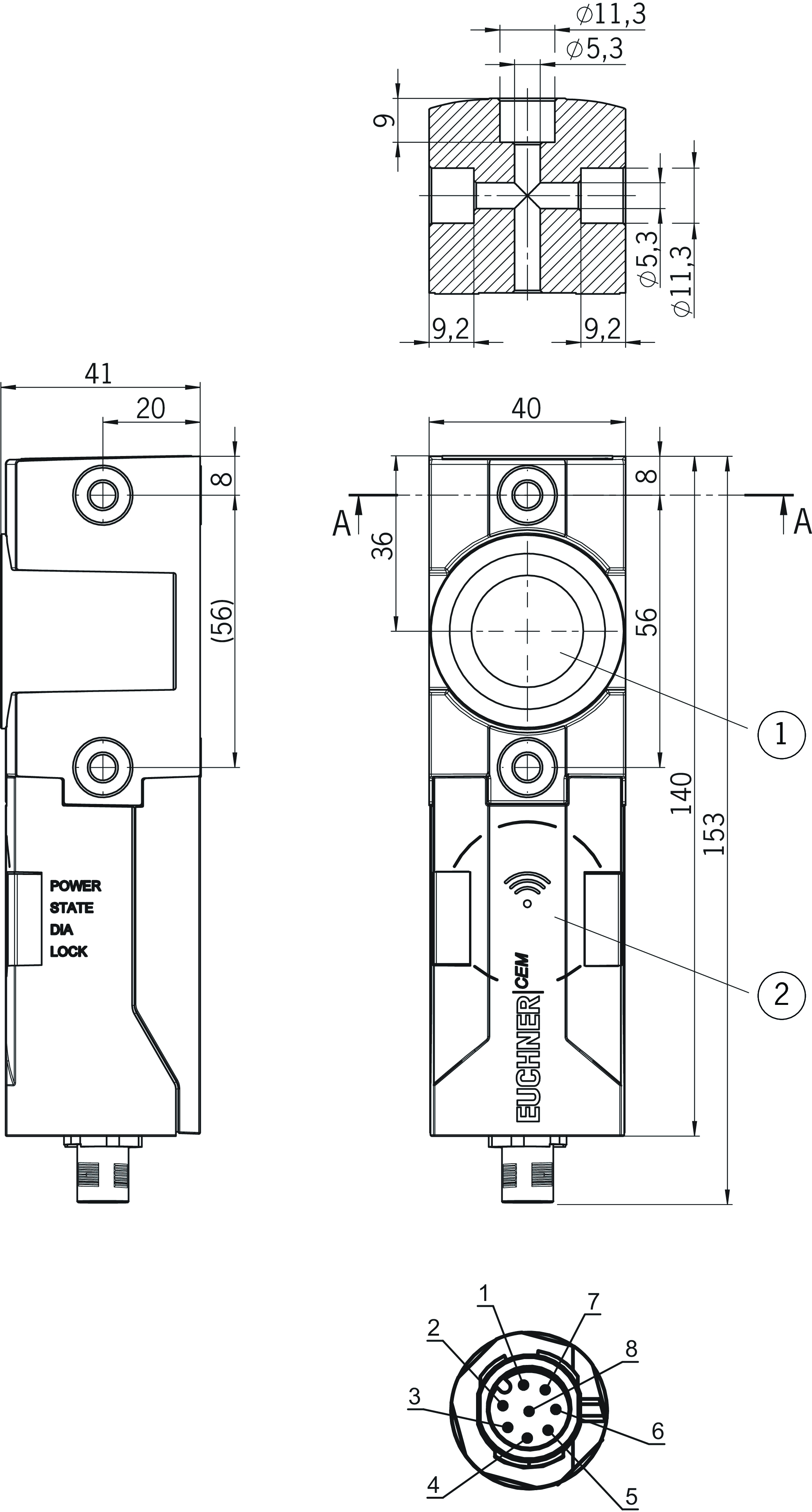
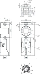
| 1 | Active solenoid face |
| 2 | Active read head face |
Connection examples
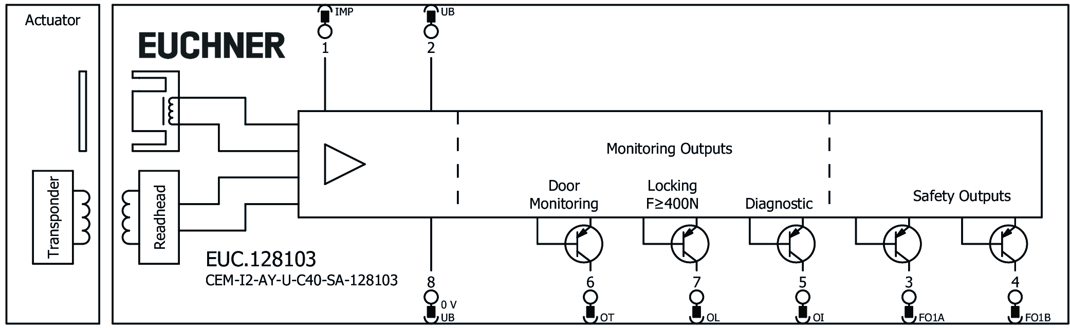
Technical data
Approvals

Workspace
| Secured switch-off distance sar | 18 mm |
| Center offset | |
| Solenoid | 5 mm (in all directions) |
Electrical connection values
| Fuse | |
| external (operating voltage UB) | 1 A |
| rated conditional short-circuit current | 100 A |
| Rated insulation voltage Ui | 30 V |
| Rated impulse voltage Uimp | 0.5 kV |
| Operating voltage | |
| DC | 24 V -15% ... +15% (PELV) |
| Discrepancy time | max. 10 ms |
| Turn-on time | 700 ... 2500 ms (Max. value, with active guard locking) |
| EMC protection requirements | Acc. to EN IEC 60947-5-3 |
| Risk time according to EN 60947-5-3 | max. 260 ms |
| Safety class | III |
| Current consumption | |
| I UB, guard locking inactive | 80 mA (Monitoring outputs not loaded) |
| I UB, guard locking active | 350 mA (Monitoring outputs not loaded) |
| Test pulse duration | max. 0.8 ms |
| Degree of contamination (external, according to EN 60947-1) | 3 |
| OT, OI, OL | |
| Output type | Semiconductor output, p-switching, short circuit-proof |
| Output voltage | 0.8 x UB ... UB V DC |
| Switching current | |
| per monitoring output | max. 50 mA |
| FO1A/FO1B | |
| Output type | Semiconductor outputs, p-switching, short circuit-proof |
| Output voltage | |
| LOW U(FO1A) / U(FO1B) | 0 ... 1 V DC |
| HIGH U(FO1A) / U(FO1B) | UB - 1.5 ... UB V DC |
| Utilization category | |
| DC-13 | DC-13 24 V 150 mA (Caution: outputs must be protected with a free-wheeling diode in case of inductive loads) |
| Off-state current Ir | max. 0.25 mA |
| Electrical switching frequency | max. 0.5 Hz |
| Switching current | |
| per output | 1 ... 150 mA |
Mechanical values and environment
| Connection type | Plug connector M12, 8-pin |
| Tightening torque | |
| Fixing screws | 4 Nm |
| Ready delay | 12 s |
| Installation orientation | any |
| Adhesive force | |
| adjustable | 0, ca. 30, ca. 50 (Auslieferungszustand 50 N) N |
| Storage temperature | -25 ... 70 °C |
| Mechanical life | |
| in case of use as door stop, and 1 Joule impact energy | 1 x 10⁶ |
| Shock and vibration resistance | Acc. to EN IEC 60947-5-3 |
| Degree of protection | IP65/IP67 (In the inserted and screwed tight state) |
| Ambient temperature | -20 ... 55 °C |
| Material | |
| Read head | Plastic (PBT) |
| Solenoid | Steel, nickel plated |
| Housing | Aluminum |
| Locking force Fmax | |
| in axial direction | 600 N (The device signals if the locking force drops below 400N.) |
Characteristic values according to EN ISO 13849-1 and EN IEC 62061
| Mission time | 20 y |
| Monitoring of the guard position | |
| Category | 4 |
| Performance Level | PL e |
| PFHD | 4.5 x 10⁻⁹ |
Accessories



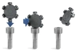
AM-C-SW3-V3-177772
- Plastic inserts for hexagon socket screws with a SW3 socket size
- Efficient protection against tampering for safety switch mounting
- The packaging includes inserts for 18 screws
AM-C-SW4-V3-161344
- Plastic inserts for hexagon socket screws a/f 4
- Efficient protection against tampering for safety switch mounting
- The packaging includes inserts for 18 screws
AM-C-SW5-V3-161348
- Plastic inserts for hexagon socket screws a/f 5
- Efficient protection against tampering for safety switch mounting
- The packaging includes inserts for 18 screws

Downloads
Complete package
Download all important documents with a single click.
Content:
- The operating instructions and any additions to the operating instructions or brief instructions
- Any data sheets to supplement the operating instructions
- The declaration of conformity
Single Documents


Other Documents


ePlan macros

Ordering data
| Ordernumber | 128103 |
| Item designation | CEM-I2-AY-U-C40-SA-128103 |
| Gross weight | 0,751kg |
| Customs tariff number | 85365019000 |
| ECLASS 11.0 | 27-27-24-05 Safety-related transponder switch with guardlocking |